

Oscilloscopes and to lesser extent indicators turbines are helpful instruments for analyzing, testing and diagnosing circuits however we frequently take without any consideration how they work. Fortunately, [FromConceptToCircuit] is right here to present us how they’re made.
[FromConceptToCircuit] begins by deciding on the {hardware} to make use of: an Artix-7-based FPGA and an FT2232 USB-serial converter. RS245 in synchronous FIFO mode is chosen for its excessive bandwidth of about 400 Mbps. Then, they present the way to wire all of it as much as your FPGA of selection. Now it’s time for the implementation; they go over how the FT2232 interfaces with the FPGA, going by way of the Verilog code step-by-step to indicate how the FPGA makes use of the hyperlink, increase from the essential transmission logic all the way in which as much as a easy framed protocol with CRC8-based error detection. With all that, the FPGA can now ship captured samples to the PC over USB.
Now it’s PC-side time! [FromConceptToCircuit] first explains the bodily pipeline by way of which the samples attain the PC: FPGA captures, transmits over RS245, FT2232 interfaces that with USB and at last, the software program talks with the FT2232 over USB to get the info again out. The software program begins by configuring the FT2232 into RS245 mode, units buffer sizes, the entire deal. With every part arrange, [FromConceptToCircuit] explains the way to use the FT2232 driver’s API for non-blocking communication.
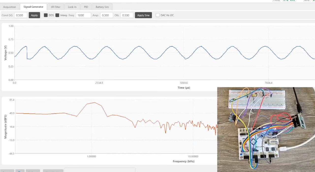
As a bonus, [FromConceptToCircuit] provides a sign generator function to the oscilloscope utilizing an I2C DAC chip. They begin by explaining what precisely the DAC does and comply with up with the way it’ll be built-in into the present system. Then it’s time to elucidate the way to implement the I2C protocol bit-for-bit. Lastly mix every part collectively for one closing demo that reveals a sine wave on the DAC’s output.